Greatest reference in our business is our successful past
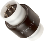
Model 110
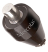
| Model 110 One Conductor, 10 Amp
|
 |
|
Mounts at the end of a rotating axis. Mount by the press fit receptacle accessory. Wire attaches using the accessory receptacle or cap. |
||

| Model No. | Terminals | Voltage AC/DC |
Amp Rating @240VAC |
Max. Freq. MHz |
Contact Resistance |
Max. RPM |
Temp Max. F (C) / Min. F (C) |
Rotation Torque (gm-cm) |
Circuit Separation |
| 110 | 1 | N/A | 10 | 200 |
|
3600 | 140 (60) /-20(-29) | 35 | N/A | ||
| 110-SS | 1 | N/A | 10 | 200 |
|
3600 | 140 (60) /-20(-29) | 35 | N/A | ||
| 110-L | 1 | N/A | 10 | 200 |
|
1200 | 140 (60) /-20(-29) | 10 | N/A |
"L" designator indicates low torque
Note: The anodized aluminum housing of the 110 series Mercotac is electrically "hot" to the internal conductor.
 |
||
| 5920 one contact receptacle |
5921-S one contact receptacle w/ 6" wire |
5952 one contact cap w/solder lug |
| 55337 ring terminal (12-10 AWG) |
||
|
Receptacle used for mounting to rotating device.
|
||

|
|
|
| Note: The metal receptacle used for mounting is electrically conductive. Therefore, if desired, it can be used as the electrical connection between the 110 and the rotating member of the machine using Part #5920. However, if an insulated mounting at the rotating member is being used, then Part #5921-S with six inch wire lead is used for the electrical connection. | |


|
||||||||||||||||||||
|
||||||||||||||||||||
 |
 |
 |
 |
 |
|
Installation Notes:
|
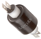
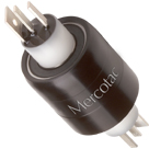
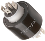
Model 110-T & 105
| Model 110-T One Conductor, 10 Amp Model 105 One Conductor, 4 Amp |
 |
|
Mounts at the end of a rotating axis. Mount by the press fit receptacle accessory. Wires attach using the accessory receptacle and cap. |
||

| Model No. | Terminals | Voltage AC/DC |
Amp Rating @240VAC |
Max. Freq. MHz |
Contact Resistance |
Max. RPM |
Temp Max. F (C) / Min. F (C) |
Rotation Torque (gm-cm) |
Circuit Separation |
| 110-T | 1 | N/A | 10 | 200 |
|
3600 | 140 (60) /-20(-29) | 35 | N/A | ||
| 110-TS | 1 | N/A | 10 | 200 |
|
3600 | 140 (60) /-20(-29) | 35 | N/A | ||
| 110-TL | 1 | N/A | 10 | 200 |
|
1200 | 140 (60) /-20(-29) | 10 | N/A | ||
| 105 * | 1 | N/A | 4 | 200 |
|
7500 | 212 (100) /45(7) | <10 | N/A | ||
| 105-SS * | 1 | N/A | 4 | 200 |
|
7500 | 212 (100) /45(7) | <10 | N/A |
"TS" designator indicates stainless steel ball bearing (recommended for wet or corrosive environments)
"TL" designator indicates low torque
"SS" designator indicates stainless steel ball bearing (recommended for wet or corrosive environments)
* indicates high temp. high RPM
Note: The anodized aluminum housing of the 110 & 105series Mercotac is electrically "hot" to the internal conductor.
|
||
| 5920 one contact receptacle |
5921-S one contact receptacle w/ 6" wire |
5952 one contact cap w/solder lug |
|
Receptacle used for mounting to rotating device.
|
||
|
|
|
| Note: The metal receptacle used for mounting is electrically conductive. Therefore, if desired, it can be used as the electrical connection between the 110 and the rotating member of the machine using Part #5920. However, if an insulated mounting at the rotating member is being used, then Part #5921-S with six inch wire lead is used for the electrical connection. | |


|
||||||||||||||||||||
|
||||||||||||||||||||
 |
 |
 |
 |
 |
 |
Installation Notes:
|
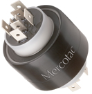
Model 1250
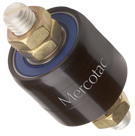
| Model 1250 One Conductor, 250 Amp
|
 |
|
| 4 jam nuts included Boot kit available Available in metric thread (1250-M) Available with stainless steel ball bearing (1250-SS) (recommended for wet or corrosive environments) Available with stainless steel body and bearing (1250-SX / 1250-MSX) (recommended for wet or corrosive environments) |
||

| Model No. | Terminals | Voltage AC/DC |
Amp Rating @240VAC |
Max. Freq. MHz |
Contact Resistance |
Max. RPM |
Temp Max. F (C) / Min. F (C) |
Rotation Torque (gm-cm) |
Circuit Separation |
| 1250 | 1 | N/A | 250 | 200 |
|
1200 | 140 (60) /-20(-29) | 250 | N/A | ||
| 1250-SS | 1 | N/A | 250 | 200 |
|
1200 | 140 (60) /-20(-29) | 250 | N/A | ||
| 1250-M | 1 | N/A | 250 | 200 |
|
1200 | 140 (60) /-20(-29) | 250 | N/A | ||
| 1250-MS | 1 | N/A | 250 | 200 |
|
1200 | 140 (60) /-20(-29) | 250 | N/A | ||
| 1250-SX | 1 | N/A | 250 | 200 |
|
1200 | 140 (60) /-20(-29) | 250 | N/A | ||
| 1250-MSX | 1 | N/A | 250 | 200 |
|
1200 | 140 (60) /-20(-29) | 250 | N/A |
"M" designator indicates metric thread (10 x 1.5)
"MS" designator indicates metric thread & stainless steel ball bearing
"SX" designator indicates stainless steel body & bearing
"MSX" designator indicates metric thread & stainless steel body & bearing
Note: The anodized aluminum housing of the 1250 series Mercotac is electrically "hot" to the internal conductor.
 |
||
| 57125 Book Kit for dust and splash protection IP51 |
||
|
|
|


|
||||||||||||||||||||||||||||||||||||
|
||||||||||||||||||||||||||||||||||||
 |
 |
 |
|
Installation Notes:
|
MERCOTAC MARKASINA A?T ?R?N GRUPLARI
1-One Conductors
2-Two Conductors
3-Three Conductors
4-Four Conductors
6-Six Conductors
8-Eight Conductors

A-Company
B-FAQ

MERCOTAC_Model 215-2K Two Conductors
PRODUCT OVERVIEW
SPECIFICATIONS OVERVIEW
Technical
USING SLIP RINGS?